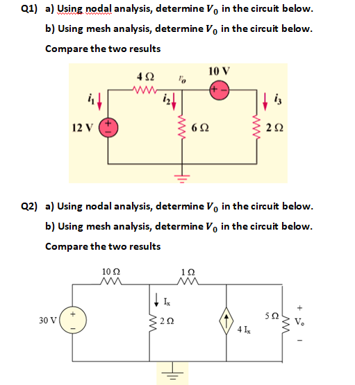
Using Nodal Analysis Determine Vo in the Circuit
824 56 1 At node 2. At node 1 latexfracV_1-4020fracV_1-020fracV_1-V_o10latex0.
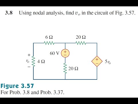
Prob 3 8 Using Nodal Analysis Find Vo In The Circuit Of Fig 3 57 Youtube
Sadiku Rent Buy.
. 20 points 3 V 9 V 3Vo 6Ω ALE. 1 Full PDF related to this paper. 2 i o v o 9 6 v 1 4 0 v o 0 8 0 0.
2 mA 3 kΩ 4 mA 4 kΩ 4 mA I 1 Figure P3. Find Vo and the power dissipated in all the resistors in the circuit of Fig. 3 Use nodal analysis to find V 1 in the circuit in Fig P3.
There are two unknown nodes as shown in the circuit below. If v1 was 50v then the current would be 50 - 40 1 10 A leaving towards ground. 30 V 20 V 4 ΚΩ Vo 2 kQ 5 kQ I I.
Since Vo is at a higher potential than V1 we have the following equation. Using nodal analysis determine the node voltages circuit shown below 3 A V 2 A 40 40 Q 20 Ω 10 Ω 6 A 3. To get currents entering the node we subtract the node voltage from other voltages so -20 - Vo8 stands for.
At node b electrically nodes b and c are same Assuming the polarity of the voltage v at node c or b we thus get. 3 Find I 1 in the circuit in Fig. Begingroup To get currents leaving a node we subtract other voltages from the node voltage.
Answer to Using nodal analysis find vo and io in the circuit of Fig. Engineering Electrical Engineering QA Library 1. 3 Find both Io and Vo in the network in Fig.
But for nodal analysis there is no such kind of limitation because each node can be assigned a voltage which is an essential parameter to analyze a node using the Node Analysis Method. Figure 361 For Prob. Using nodal analysis determine Vo in the circuit in Fig.
At the top node KVL. Use nodal analysis to determine Vo in the following circuit. 10Ω 20Ω w 10Ω 20Ω 40V 41 HI.
Answer to Using nodal analysis determine Vo in the circuit in Fig. P3 using nodal analysis. Node voltages and identify the supernode as shown in Fig.
6Ω 12 Ω Ww 24 V 12 Ω 60 V v1 and v2 and the currents ij i2 i3 and i4 in the 2. Using nodal analysis determine Vo in the circuit in Fig. Using nodal analysis determine Vo in the circuit in Fig.
3 Use nodal analysis to find V 1 in the circuit in Fig. Using nodal analysis determine vo in the circuit shown below. Let V1 be the unknown node voltage to the right of the 250-Ω resistor.
358 using nodal analysis. 2007 The McGraw-Hill Companies Inc. 9 Vx 6 Vx Vk Vx 6 1k 4k 2k Vx.
Chapter 10 Solution 3. 350 using nodal analysis. Determine Ib in the circuit in Fig.
6 kΩ 2 mA 3 kΩ 12 kΩ Io. Fundamentals of Electric Circuits 7th Edition Edit edition Solutions for Chapter 3 Problem 12P. 0175v_ 1 0225v_ o 824 56 0175v1.
Calculate voltage V in circuit of Fig1 using Nodal analysis. To get a third equation we notice the nodes at V1 and Vo and how the two nodes are separated by the voltage source. Use Nodal Analysis to determine vo in the circuit.
Determine vo in the circuit of Fig. Using nodal analysis determine vo in. Use nodal analysis to determine Vo in the following circuit.
So the v1 - 401 represents the current leaving node 1 along that branch eg. 20 points 3 V 9 V 3Vo 6Ω ALE. V_ 312angle 0 V_ 1 V 3.
1 kΩ 4 kΩ Ix 9V 2 kΩ _ 6V _ Figure 350 For Prob. But Substituting this into the nodal equation leads to Thus Example 2. 2i_ o v_ o96v_ 140 v_ o080 0 2io.
96 6 14 2 xxk x VVV V kkk 3 mA 2 x x V I k PROPRIETARY MATERIAL. Applying nodal analysis 1 6 j8 2 4 j3 - j16 o o o V V V 6 j8 o 1 4 j3 1 2 1 4 j3 - j16 V. Chapter 3 Problem 1.
Using nodal analysis determine the node voltage Vo in the circuit shown below. Fundamentals of Electric Circuits 5th Edition Edit edition Solutions for Chapter 3 Problem 12P. Figure 361 For Prob312.
9780077436445 9780077575915 9780077753603 9780077800765. 1 Nodal Analysis To perform a nodal analysis we label the. Determine Ix in the circuit shown in Fig.
Fundamentals of Electric Circuits 3rd Edition Edit edition Solutions for Chapter 3 Problem 12P. Let the ground reference be placed at the bottom of the 50-Ω resistor. MathbbV_o - mathbbV_1 12 angle 0circ qquadEqn3.
1 Answer to Using nodal analysis determine Vo in the circuit in Fig361. -j 10 120 v 1 40 A 10 10 I 21 jin Vo Figure 1. 350 using nodal analysis.
Using Nodal method find the current through resistor r2 Figure 1. In node analysis the first step is to identify the number nodes exist in a circuit network whether it is planer circuit or non-planer circuit. 722bThe constraint equation for the supernode is.
Determine Ix in the circuit shown in Fig. November 14 2017 in Electricity tagged Basic Engineering Circuit Analysis - 10th Edition BECA - Chapter 3 Use nodal analysis to find both V1 and Vo in the circuit in Fig 36. 1 kΩ 4 kΩ _ Ix 2 kΩ _ 9 V 6 V Figure 350 For Prob.
Figure 1052 For Prob. Nelms Basic engineering circuit analysis 10th ed. Vo 4 mA.
Chapter 3 Solution 1 Let Vx be the voltage at the node between 1-kΩ and 4-kΩ resistors. Figure 379 SolutionInn. Using Thevenin theorem find Vo in the circuit shown in Fig1.
ω4 2 cos4t 20 16sin4t 16-90-j16 2 H jωL j8 -j3 j4112 1 j C 1 1 12 F ω The circuit is shown below. V 3 1 2 0 V 1. Chapter 3 Solution 1 Let Vx be the voltage at the node between 1-kΩ and 4-kΩ resistors.
Let us redraw the circuit with naming of the nodes and branch current as shown in figure 2.

Using Nodal Analysis Determine Vo In The Circuit In The Figure Holooly Com

Use Nodal Analysis And Matlab To Find Vo Circuit Analysis Analysis Physics Notes Dc Circuit
Solved Q1 A Using Nodal Analysis Determine Vo In The Chegg Com


Comments
Post a Comment